...
Configuration | Range | Measurement | Default | Description |
| I2C settings | Configures I2C on the TSM | |||
| Address0 | to 1278 to 119 (0x8 to 0x77) | 7-bit value | 80 (0x50) | The I2C I2C address for the TSM. NOTE: Addresses 0-7 and 120-127 are I2C reserved addresses and should not be used. |
| System Enabled | Configures the startup state of the TSM | |||
| System Enabled | True/False | Boolean | True | Enables or disables the TSM |
| Operation Mode | Configures the default operation mode | |||
| detection | True/False | Boolean | True | Operation mode ASN.1 over either I2C or USB Raw HID |
| detectionHID | True/False | Boolean | True | Operation mode USB HID |
| Range Settings | Sets the scanning range dynamically | |||
| Scanning Range | 10-1·mm | Mechanical Data (col. B * 10) | The area (width and height) the Touch Sensor Module (TSM) will scan for an object with lasers and photodiodes (PD). This value also sets the limit for High Y (Max Y) below. | |
| Frequency Settings | Changes the Touch Sensor Modules update frequency | |||
| Idle Frequency | Frequency | Hz | 33 | Scanning frequency when the Touch Sensor Module has not registered any touch object. |
| Finger Frequency | Frequency | Hz | 100 | Scanning frequency when the Touch Sensor Module has registered and tracking a touch object. |
| Touch Active Area Adjustments | Contains settings for modifying the active touch area and the reported touch coordinates | |||
Low Bound X (Min X) | 10-1·mm | 36 | Start position of the Touch Active Area (TAA) in X-direction. Low X, High X, Low Y & High Y make up the TAA. | |
Low Bound Y (Min Y) | 10-1·mm | 0 | Start position of the Touch Active Area (TAA) in Y-direction. Low X, High X, Low Y & High Y make up the TAA. | |
High Bound X (Max X) | 10-1·mm | Mechanical Data (col. A * 10) + 36 | End position of the Touch Active Area (TAA) in X-direction. Low X, High X, Low Y & High Y make up the TAA. | |
High Bound Y (Max Y) | 10-1·mm | Mechanical Data (col. B * 10) | End position of the Touch Active Area (TAA) in Y-direction. Low X, High X, Low Y & High Y make up the TAA. | |
Reverse X | True/False | Boolean | False | Reverses the X-coordinates of reported touches. Note, that the origin of the vast majority of the displays is in the top left corner. |
Reverse Y | True/False | Boolean | False | Reverses the Y-coordinates of reported touches. Note, that the origin of the vast majority of the displays is in the top left corner. |
Flip XY | True/False | Boolean | False | Swaps the Y- with the X-coordinates of the reported touches. |
Offset X | 10-1·mm | 0 | Offsets the projected TAA in X-direction, on the display. | |
Offset Y | 10-1·mm | 0 | Offsets the projected TAA in Y-direction, on the display. | |
| HID Display Size | The size of the display reported by the Touch Sensor Module to the host. Only usable when connecting with USB HID | |||
Hid Display Size X | 10-1·mm | Mechanical Data (col. A * 10) | Width of the physical display. It is very important to set this parameter correct since the TSM will report touch coordinated in percentage of the physical display length/height. | |
Hid Display Size Y | 10-1·mm | Mechanical Data (col. B * 10) | Height of the physical display. It is very important to set this parameter correct since the TSM will report touch coordinated in percentage of the physical display length/height. | |
| Snapping | Configure the snapping area around the edges of the Touch Active Area (TAA) | |||
| Enabled | True/False | Boolean | False | Enables or disables the snapping filter. |
| Left Inner | Mechanical Data | 10-1 mm | 0 | Distance from edge to the inner snapping edge, left side of TAA. |
| Left Outer | Mechanical Data | 10-1 mm | 0 | Distance from edge to the outer snapping edge, left side of TAA. |
| Right Inner | Mechanical Data | 10-1 mm | 0 | Distance from edge to the inner snapping edge, right side of TAA. |
| Right Outer | Mechanical Data | 10-1 mm | 0 | Distance from edge to the outer snapping edge, right side of TAA. |
| Top Inner | Mechanical Data | 10-1 mm | 0 | Distance from edge to the inner snapping edge, top side of TAA. |
| Top Outer | Mechanical Data | 10-1 mm | 0 | Distance from edge to the outer snapping edge, top side of TAA. |
| Bottom Inner | Mechanical Data | 10-1 mm | 0 | Distance from edge to the inner snapping edge, bottom side of TAA. |
| Bottom Outer | Mechanical Data | 10-1 mm | 0 | Distance from edge to the outer snapping edge, bottom side of TAA. |
| Click On Touch | Configures the Touch Sensor Module to send an Up (touch event) after Down within a defined threshold to create an instant touch experience | |||
| Enabled | True/False | Boolean | False | Enables and disables the Click On Touch Feature |
| Time To Up | ms | 100 | Time from the Down event until the Up event is sent. | |
| Distance | 10-1·mm | 100 | Distance from the initial location that a touch must stay within for Click On Touch to be enabled for a touch | |
| Floating Protection Settings | Wait for the object to stabilize on the Y-axis, in order to identify the position of the object in a reliable way. This parameter should not be set at the same time as Double-Click Prevention is turned on. | |||
| Enabled | True/False | Boolean | True | Floating protection enabled. |
| Floating Protection Time | ms | 40040 | Time to wait before reporting touch registration. | |
| Double-Click Prevention Settings | Configuration of the filter prevention area and timeout. This parameter should not be set at the same time as Floating Protection is turned on. | |||
| Enabled | True/False | Boolean | False | Enables or disables the double-click prevention filter. |
| Prevention Time | >0 | ms | 500 | The time period when no additional touches will be reported in prevention area. |
| Prevention Radius | >0 | 10-1 mm | 220 | The radius of the area around the touch defining area where touches are suppressed. |
| Object Size Restrictions | Only reports touches with an object size that is within the defined limits | |||
Max Size Enabled | True/False | Boolean | False | Allows a maximum touch object size. |
Max Size | 10-1·mm | 0 | Max limitation of a touch object (if Max Size Enabled =True). | |
Min Size Enabled | True/False | Boolean | False | Allows a minimum touch object size. |
Min Size | 10-1·mm | 0 | Min limitation of a touch object (if Min Size Enabled =True). | |
| Miscellaneous Settings | ||||
Number Of Reported Touches | 1-10 touches | Quantity | 2 | The number of touches that can be reported simultaneously. |
| Reflective Edge Filter | True/False | Boolean | False | Useful when there is a risk that there are highly reflective materials right outside the active touch area |
...
Scanning Range defines the Scanning Area of the sensor. For the definition of Scanning Area, refer to TSM - Definitions. This setting can only be changed through the zForceProgrammer. The Scanning Range can beset to a lower ((shorter range) value. It can also be set to a higher value than the default if the TSM FirmWare (FW) allows Extended or Maximum Range in Y-axis. As default the Scanning Range is set to a DefaultRange, see Mechanical Data, Table 1 for the values., Table 1 for the values.
Scanning Range parameter can be saved in .json configuration file and then written/flashed back to the sensor. The parameter is called Peak Count
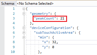
and has the following correlation with the Scanning Range:
| Scanning Range | Peak Count |
| 149 | 3 |
| 298 | 4 |
| 447 | 5 |
| 596 | 6 |
| 745 | 7 |
| 894 | 8 |
| 1043 | 9 |
| 1192 | 10 |
| 1340 | 11 |
| 1489 | 12 |
| 1638 | 13 |
| 1787 | 14 |
| 1936 | 15 |
| 2085 | 16 |
| 2234 | 17 |
| 2383 | 18 |
| 2532 | 19 |
| 2681 | 20 |
| 2830 | 21 |
| 2979 | 22 |
| 3128 | 23 |
| 3277 | 24 |
Frequency Settings
The frequency parameters set the various scanning frequencies. The maximum scanning frequencies are depending on the product variant.
...
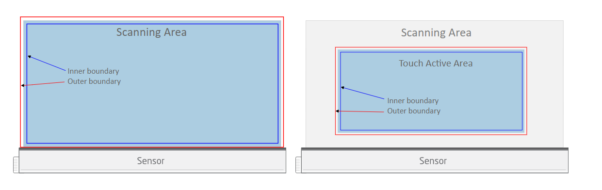
Touch Active Area is the selected (configured) area of the Scanning Area that the TSM will report touches from (TSM - Definitions).
Axis Orientation
When mapping a reported touch from the Touch Active Area (TAA) to a display, it is important that the orientation of the TAA, as well as the display are taken into account. When positioning a Touch Sensor Module over a display to achieve touch functionality, both systems needs to be co-aligned in order for a reported touch to be projected in the same corresponding position of the screen. If both systems are not oriented in the same way, the reported touches are going to be reversed depending of the setup. Luckily, the orientation of the reported touches can be configured to counter this by using ReverseX/ReverseY or FlipXY in Device Configuration. These settings rotates or flips the given coordinates of the reported touches, which allows the Touch Sensor Module to be mounted at any of the 4 sides of the screen
...
When the snapping filter is enabled, an outer- and inner distance to the edge of the scanning area can be configured. It can be configured for the left, right, top and bottom edge of the scanning area with the unit of 10-1 mm. When a touch is detected between the inner- and outer distance regions, the reported touch location is snapped to the edge of the configured touch area.


Click On Touch
...
Time from the down event until the up event is sent. Setting this to 0 completely disables the possibility to do swiping gestures (or drawing). Setting this to e.g 100ms 100 ms gives the end user 100ms 100 ms to move outside of the set Distance (described below) and begin the swipe gesture instead.
...
This value indicates how long this filter would need to validate the first reported touch. Default value is 400 40 ms. With a lower value the risk increases that a false touch would be reported, and the opposite with a higher value.
...
The filter is designed to prevent multiple touches within a defined area for a short period of time. Both the prevention radius (10-1 mm) and the prevention time (ms) are configurable parameters.
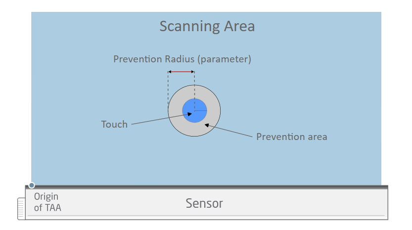

When enabled the system will define a prevention area for each touch and will not react to additional touches in those areas until the prevention time has expired. This way undesired double-clicks can be prevented for a certain area while maintaining quick response times outside of the prevention areas on the TAA.
...
This is a Boolean value to disable or enable the reflective edge filter. This filter is useful when there is a high risk that there will be a highly reflective materials right outside the Touch Active Area. In the presence of such materials there is a risk that the Touch Sensor Module will report it as a touch within Touch Active Area. An example of a highly reflective material could be a white paper or something similar.
| Panel | ||||||
|---|---|---|---|---|---|---|
| ||||||
|