Required Equipment
The following equipment from the evaluation kit is required:
| Include Page | ||||
|---|---|---|---|---|
|
...
|
Additional required equipment:
- Computer
- Operating system: Windows 8.1, Windows 10 or Windows 1011.
- Software requirements: .NET Framework 4.5 or higher is required and can be downloaded from Microsoft's official website. Windows 8 and higher has this installed by default.
USB cable with a Micro USB type B connector
Warning Make sure that the USB cable transmits both power and data and not only power.
- (Optional) tape for mounting
Connecting Sensor Module
- Connect the FPC cable to the interface board:

- Lift the flip lock on the interface board.
Insert the FPC cable into the end of the connector, with the connector pads facing down, towards interface board. The yellow piece of PCB of the connector on the other side of the cable is facing upwards. Make sure the direction is straight into the connector and the pads have reached the end of the connector.
Make sure the connector pads of the FPC cable are facing downwards, towards interface board. The sensor module risks damage if the FPC cable is connected in wrong direction.
Press down the flip lock.
- Connect the FPC cable to the sensor module:

It is very important to be careful when connecting the sensor to a FPC cable! No excessive force may be applied! No bending is allowed! This may cause the PCB to detach or break.
- Place the sensor module so that the module's connector pads are facing downwards (steel surface upwards).
- Insert the sensor module into the connector on FPC cable (yellow piece of PCB of the FPC connector still facing upwards).
- Make sure the direction of the pads is straight into the connector, and the pads have reached the end of the connector.
Connect a USB cable with a Micro USB type B connector to the interface board.

Make sure no object is within the touch active area of the sensor module before connecting power to the sensor through USB. The sensor calibrates itself when powered on and an object within the touch active area may interfere with the calibration.
If the sensor module is of the 0° type: place the module on a table with the steel surface facing downwards and with the optical surface facing towards you.

If the sensor module is of the 90° type: place the module on a table with the steel surface facing upwards, so the optical surface is facing upwards as well. Make sure no object is within the touch active area above the sensor module.

Alternatively, you can mount the sensor module by using tape in order to fasten the steel surface to the edge of a table, with the optical surface facing towards you.

Insert the USB cable into a computer.

The green LED on the interface board lights up when connected.

Connecting Sensor Module
| Include Page | ||||
|---|---|---|---|---|
|
Install and Open Neonode Workbench
- Download the latest release of the Workbench installation package from Downloads.
- Unzip the installation package.
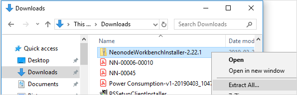
- Open the installation package folder.
- Run the Workbench installer (.msi file) and follow the instructions.
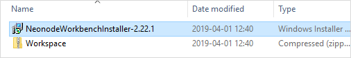
- Open the installation package folder again.
Unzip the Workspace folder to a location where you have write permissions. Write permissions are required to save settings and user data.
Info In order for the Workbench application to operate, the files in the Workspace folder must be kept together. Move the entire folder if you want to relocate the workspace file.
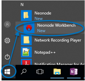
- Open the Neonode Workbench application.
- From the toolbar, select File >> Open Workspace.
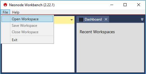
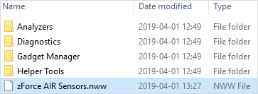
- Navigate to the Workspace folder and double-click the .nww file inside the folder.
...
For further information, please refer to Workbench documentation.
| Panel | ||||||
|---|---|---|---|---|---|---|
| ||||||
|