Prerequisites
Hardware requirements
CPU : 1 GHz
RAM: 512 MB
Disk space: 20 MB
Operating System requirements
Windows 8.1, Windows 10 or Windows 11.
Software requirements
.NET Framework 4.5 or higher is required and can be downloaded from Microsoft's official website. Windows 8 and higher has this installed by default.
Installing Neonode Workbench
- Download the Workbench installation package here.
- Unzip the installation package.
- Open the unzipped installation package folder.
- Run the Workbench installer (.msi file) and follow the instructions.
- Open the installation package folder again.
Unzip the Workspace folder to a location where you have write permissions. Write permissions are required to save settings and user data.
In order for the Workbench application to operate, the files in the Workspace folder must be kept together. Move the entire folder if you want to relocate the workspace file.
Opening a Workspace
- Open the Neonode Workbench application.
- From the toolbar, select File >> Open Workspace.
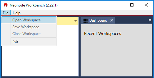
- Navigate to the Workspace folder and double-click the .nww file inside the folder. Items appear in the left panel, Workspace Explorer.
Navigating the Workspace
The main parts of the Workspace are
- The left panel Workspace Explorer, which contains all the items (information, configuration, and tools) in the currently loaded workspace. Double-click on an item to open it.
- The right panel, which shows the content of each opened item on a separate tab. You can collapse and expand content by clicking the icons
 and
and  . The Dashboard tab is the default tab.
Status or error information appear on occasion in the top center of the Workbench application. For example, a status notification appears when a Touch Sensor Module (previously referred to as zForce AIR) is connected or disconnected.
Accessing Sensor Module Information
In the left panel, double-click the item zForce AIR Sensor Gadget. The sensor module information such as firmware version, protocol version, etc shows in the right panel.In the left panel, double-click the item zForce AIR Sensor Device. Two sections, Control Panel and Device Configuration, show in the right panel.
- In the right panel, click the Is Enabled checkbox to enable or disable the sensor.
- Select communication mode in the Mode dropdown list:
- Select Detection to send touches to Workbench.
- Select DetectionHID to send touches to the operating system. The sensor module acts as a USB HID Touch Digitizer unit.
Configuring the Sensor Module
- In the left panel, double-click the item zForce AIR Sensor Device. Two sections, Control Panel and Device Configuration, show in the right panel.
- In the right panel, click the Is Enabled checkbox to enable or disable the sensor module.
- Select communication mode in the Mode dropdown list:
- Select Detection to send touches to Workbench.
- Select DetectionHID to send touches to the operating system. The sensor module acts as a USB HID Touch Digitizer unit.
- Configure the available sensor module's parameters.
- Click Send Configuration to activate the selected configuration. The activated configuration is stored temporarily in the workspace.
- Optional: to save the configuration for future sessions, select File >> Save Workspace.
Automatically Send the Saved Configuration to the sensor module upon Connection
Check the box Send Saved Configuration On Connect. The next time a sensor module connects, Workbench sends the currently saved configuration directly to the module. This can be useful since the configuration is stored in RAM on the sensor module, which means that the sensor module will go back to default configuration after a power reset.
Restore the original configuration
Click Set Original Configuration to change the configuration of the sensor module back to the configuration that the module had when it first was connected to Workbench.
Available parameters
For a list and description of available parameters, refer to Parameters Overview.
Testing the Sensor Diodes with an Open/Short-Circuit Test
- In the left panel, double-click the item Open Short Test.
- In the right panel, select the zForce AIR Sensor Gadget to test:
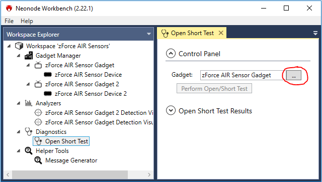
- Click the button to perform an open short test on all photo diodes and laser diodes.
When the test is completed, the result appears in the right panel. Each component that was tested is represented by a box with a number inside it. The box will either be green which indicates that the test has passed, or red for fail.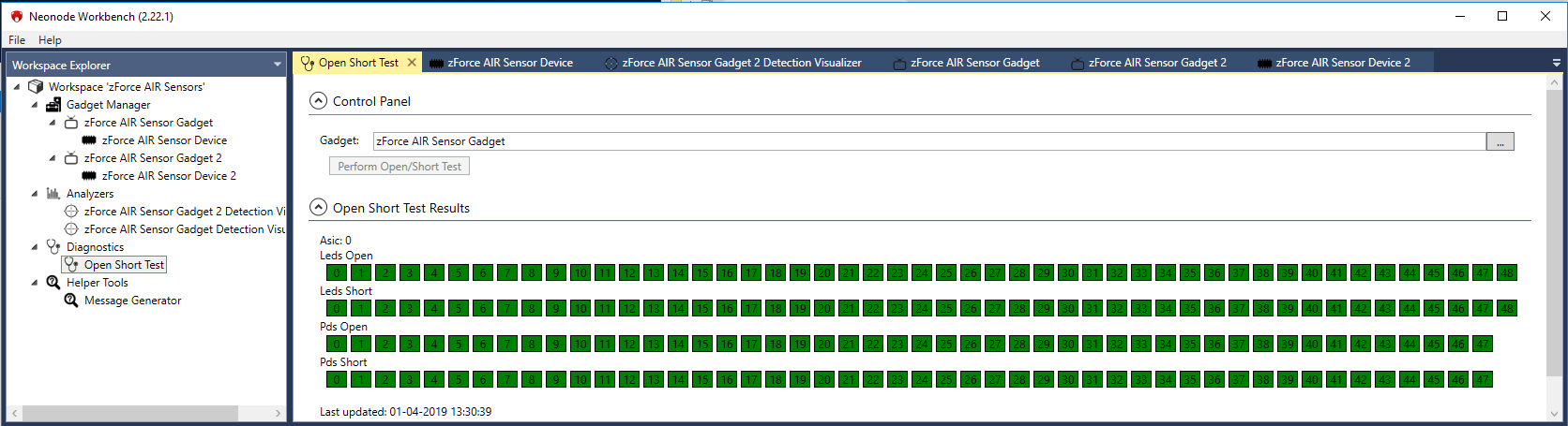
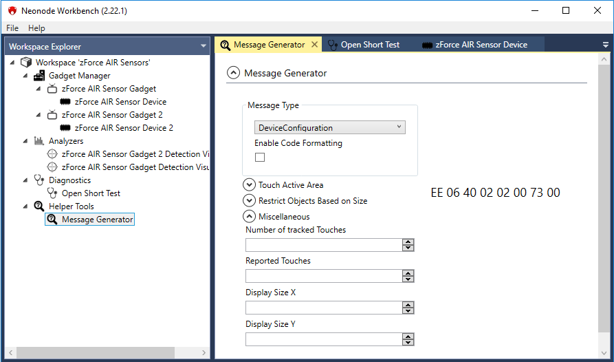
Message Generator
The sensor module exchanges information in messages that are structured and encoded according to the ASN.1 standard. The Message Generator tool helps you to generate ASN.1-messages in hexadecimal format. This can for example be useful when you use a microcontroller unit as host for the sensor module, and you need to send a specific message.
- In the left panel, double-click the item Message Generator Tool.
- In the right panel, select Message Type in the dropdown list.
- Select and set the parameters to include in the message. Click the expand icon(s) to see all the parameters that are available for the selected message type. The generated message shows to the right of the settings and is updated instantly when a setting changes.