Product Overview
The Neonode Touch Sensor Module (previously referred to as zForce AIR) is a laser light based touch sensor module that can be integrated and used in various applications. The sensor module's characteristics are high scanning frequency, low latency, good touch accuracy and it can be used on any surface or even in-air. The Touch Sensor Module can be connected to the host system through a standard connector and communicate through a standard I2C or USB interface.

Main Features
Enables touch on any surface or in-air
Multi-touch support
High scanning frequency – up to 200Hz or more depending on sensor modules length
Low touch latency
High touch accuracy
Idle mode for reduced current power consumption
Configurable touch active area
I2C and USB interface
Standard 5V power supply
Product handling
Connecting the Touch Sensor Module
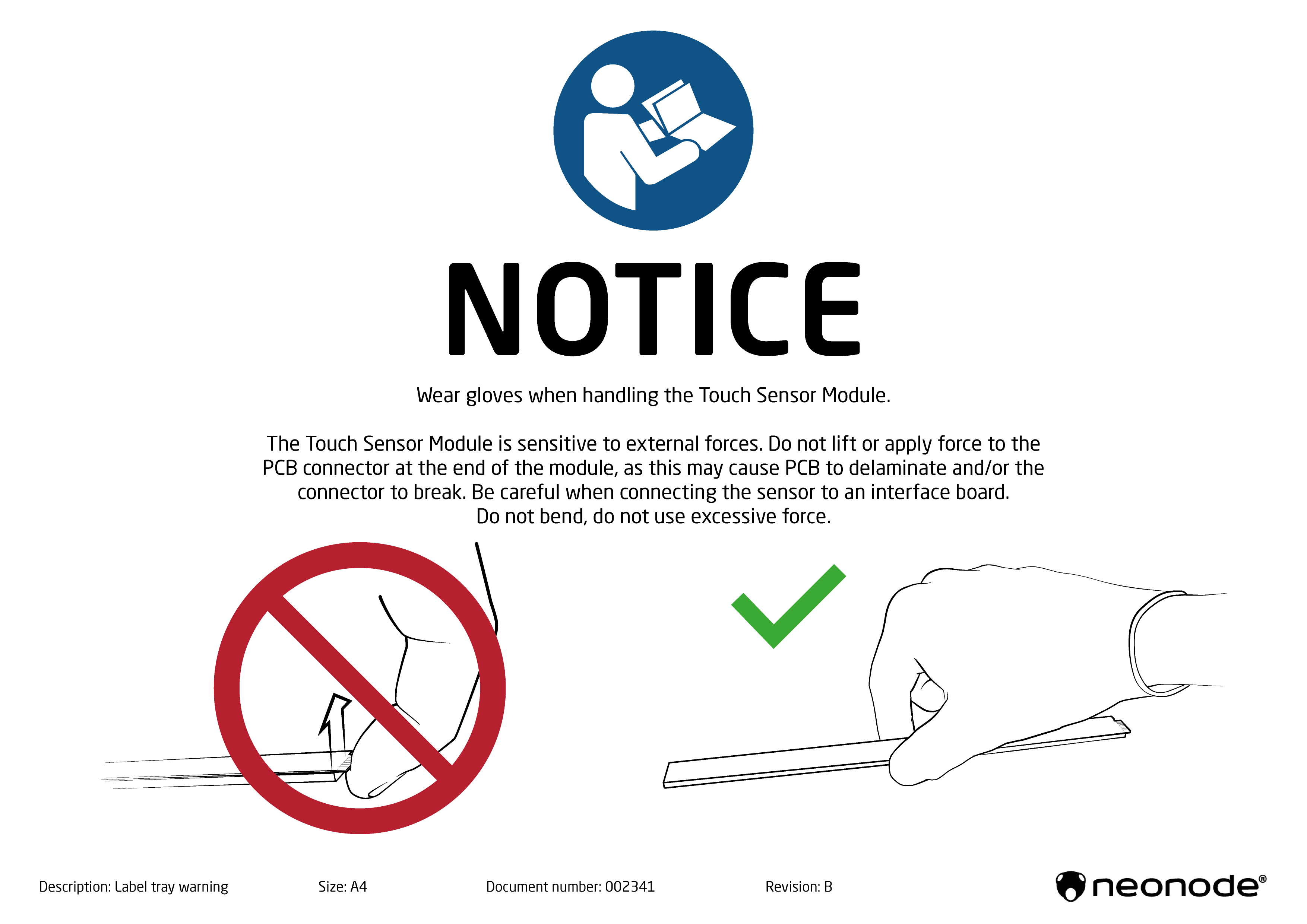
Be careful when connecting the Touch Sensor Module!
Please observe that it is important to be careful when connecting the sensor to an FPC cable such as no excessive force may be applied, no bending of contact is allowed. This may cause the PCB to delaminate or/and the contact to break.
Since the sensor is an optical device wear gloves when handling the Touch Sensor Module to prevent blurring the light guide plate!
Electrostatic Sensitive Device
Electrostatic Sensitive Device!
To prevent equipment damage, use proper grounding techniques.
Product Variants
In order to fit in a wide range of applications, the Touch Sensor Module exists in two types, one for horizontal and one for vertical integration, and a number of different lengths.
If the variant you are interested in is not available for purchase from your distributor, please contact the distributor or a Neonode sales representative (refer to www.neonode.com) for more information.
Sensor Module Orientation
The Touch Sensor Module is available in two types, one where the active area emerges straight out from the sensor module (0° type) and one where it emerges out from the sensor module at a 90° angle (90° type). This enables both vertical and horizontal integration.
0° Type

90° Type

Sensor Module Length
The Touch Sensor Module is available in 43 different lengths. The length affects the Touch Active Area (TAA) in both X and Y directions.
Touch Active Area
The tables that list all product variants with the product numbers, the TAAs, and, if applicable, the TAA with Extended Range for each variant can be found in Mechanical Data.

Basic Principles
The Neonode Touch Sensor Module detects and traces objects by detecting diffusely reflected infrared light. The sensor module comprises an optical system arranged to combine emitted IR beams and receiver fields of view within the same apertures. IR light beams are emitted perpendicular to the output window, while receivers field of view is centered at a certain angle left and right.
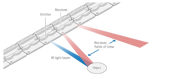
Each emitter-receiver combination covers a narrow region on the active area. An object present in the active area will affect several emitter-receiver channels, and the reported coordinates is the outcome of a center of gravity calculation on these signals.
Multi-Touch Functionality
The Touch Sensor Module determine an object's position by signals derived from emitter-receiver pairs and have the capacity to detect and track several objects at the same time. Both the hardware and the software have been optimized in order to support standard touch gestures like, pinch-to-zoom, rotate, swipe and tap. However, some combinations of two or more objects might require special consideration, which is described in more detail below.
Shadows

- An object directly behind another object cannot be illuminated. In the figure above, object A will not be detected since illumination is blocked by object B.
- The correct receiver must have a clear field of view. Object B is in a region covered only by left looking receivers. Object B will not be detected because its field of view is blocked by object D.
- Object C may be seen by both left and right looking receivers. Although the right looking field of view is blocked by object D, object C is detected by the left looking receiver.
- Object D is detected by both left and right looking receivers.
Shadow Trick
Note that in most cases, user experience is not affected by the shadow situations mentioned above. This is because of a functionality implemented in the sensor module's firmware called "shadow trick", which e.g. generates a smooth "rotate" feeling despite one touch object being shadowed during the rotate gesture. A previously detected object that can no longer be detected is still reported as present if:
- The object was last seen close to a location where it could be shadowed by another object.
- The potentially shadowing object is still detected and hasn't moved away from a shadowing location.
The shadow trick make multi-touch gestures such as "rotate" and "pinch-to-zoom" work better.
Adjacent Objects

- In order to recognize two objects close to each other (A and B), a separation must allow at least one emitter-receiver channel (~10 mm) to pass freely between them. Otherwise, the two objects will be reported as one large object.
More Than Two Objects
When more than two objects are being tracked the likelihood that an object ends up being in the shadow of another object increases. Therefore, it is only recommended to enable more than two tracked objects if, for example:
- it is not vital to track all detected objects 100% in all possible combinations and locations at all time.
- When all objects are likely to be detected by the sensor module, for example when it is expected that all objects will be placed along a line that is parallel to the sensor module, as in the example below.

Applications
The Touch Sensor Module can be integrated for a wide range of applications, such as:
- PCs/Tablets
- TVs/Monitors
- Printers
- Mechanical key replacement
- White goods
- Smart furniture
- Interactive mirrors
- Elevator panels
- eReaders
- Instruments
- Vending Machines
- ATM/POS terminals
- Robotics
- Range finders
- Collision detectors
- ... and much more
Sensor Module Design and Components
The Touch Sensor Module is a laser light based touch sensor module that can be used for various touch and in-air detection applications. The image below show the sensor module design (0° type). The connector is shown to the far right.

Exploded view
The image below shows the sensor module (0° type) in an exploded view.

Part | Description |
|---|---|
A | Cover |
B | Adhesive |
C | Front light pipe – straight shooting or 90 degree shooting depending on sensor module's type |
D | Lenses - the amount depends on sensor module's length |
E | PCBA |
Sensor Module Components
The PCBA is equipped with both active and passive components, for example:
- MCU
- Co-processor, a Neonode proprietary scanning IC
- Optical lenses, made out of polycarbonate
- VCSELs
- Photodiodes
- Other passive components
Product Integration
The Touch Sensor Module can be integrated into any host system through a physical connector with 8 contact pads. The connector supports both I2C and USB HID.
The sensor module communicates with messages that are defined in ASN.1-notation. ASN.1 is a standardized way (ISO/IEC 8824) to describe data regardless of language implementation, hardware system and operation system. The host system can communicate with the sensor module using the zForce communication protocol.
To facilitate integration, Neonode has developed function libraries that are available for download.