Created by Unknown User (nike.olabiyi), last modified on Jan 25, 2024
To be able to understand the descriptions given in this section, it is suggested to first get acquainted with the definitions explained in Parameter Overview.
Use Case
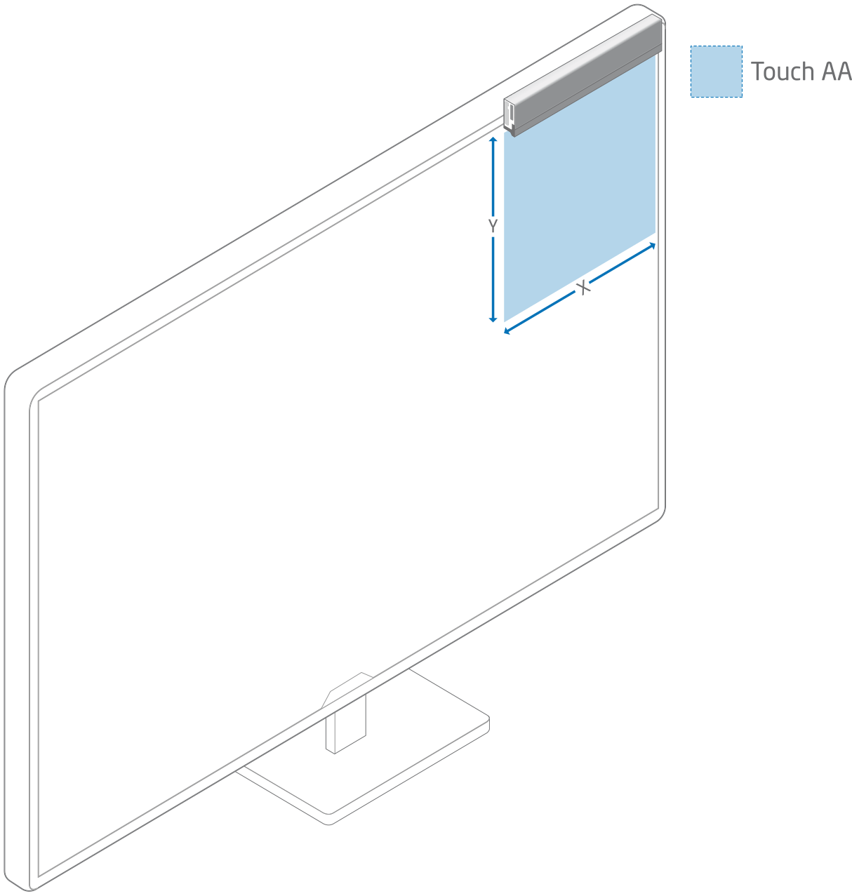
This method of configuring sensor module(s) can be used to get one or multiple touch areas on a larger screen or on a large projected area, further referred to as Screen.
Illustrations
Introduction
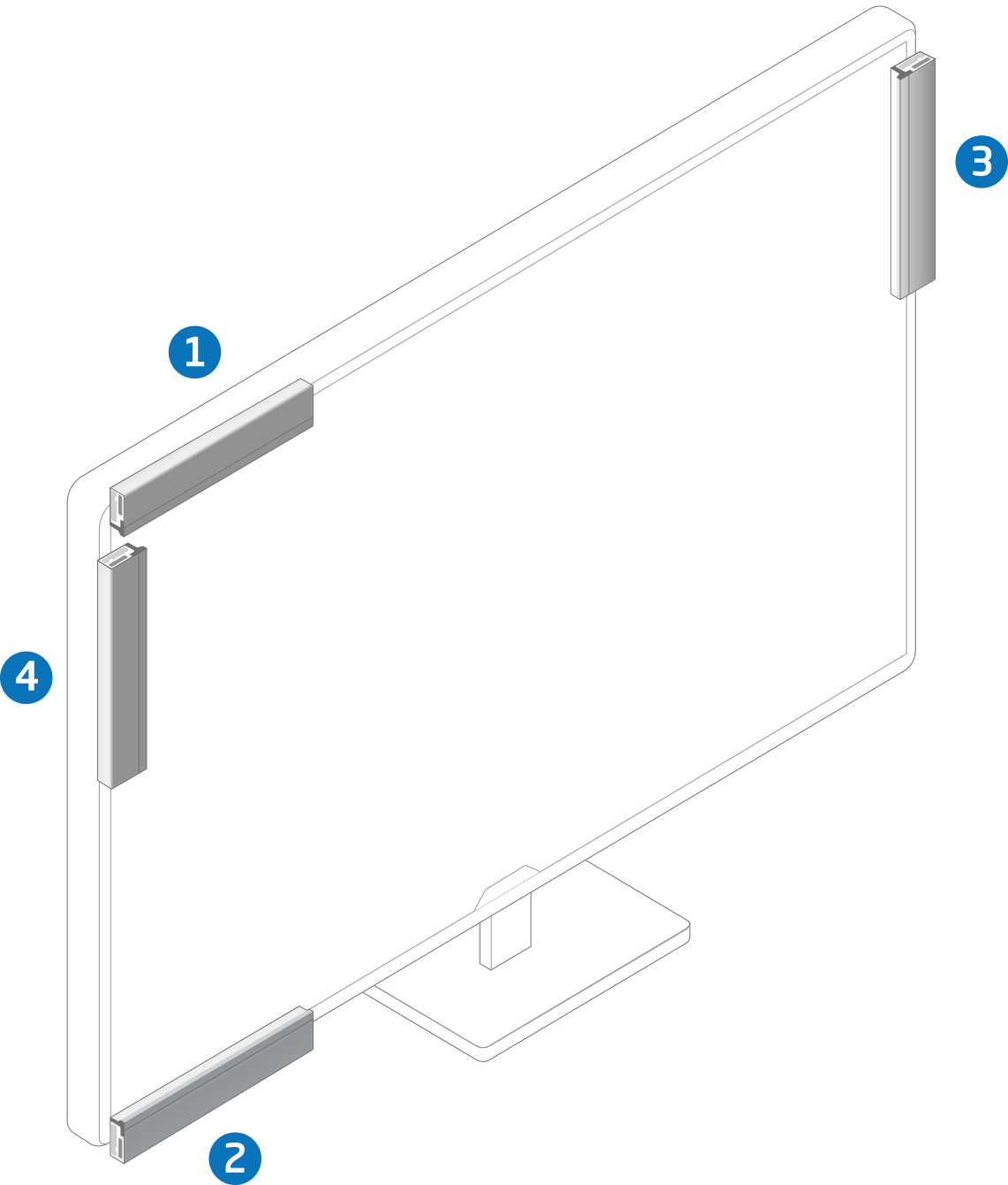
A Touch Sensor Module can be mounted on four sides of a screen and with the connector to either the right or the left (PCB or silver side down) but we recommend mounting it with the silver side towards the screen, as the touch area is then closer to the screen.
This will give a total of eight different configurations.
It is possible to mount a sensor module "on" or "in" the screen. However this will cover/block part of the screen and is therefore not a part of this example.
Top: Sensor module on top of the screen facing down.
Bottom: Sensor module on bottom of the screen facing up.
Right: Sensor module on right side of the screen facing left.
Left: Sensor module on the left side of the screen facing right.
HID Display Size
HID Display Size is the physical size of the screen in tenths of millimeters (1/10 ; 1 mm = 10)
Configurations With One Sensor Module
NOTE: Values in bold has to be changed from default to make the configuration work.
Configuration
1 (Top - Connector to the right)
Selected Area Lower Bound X
<Default values from sensor modules original configuration>
Selected Area Lower Bound Y
<Default values from sensor modules original configuration>
Selected Area Upper Bound X
<Default values from sensor modules original configuration>
Selected Area Upper Bound Y
<Default values from sensor modules original configuration>
Selected Area Reverse X
True
Selected Area Reverse Y
False
Selected Area Flip XY
False
Selected Area Offset X
The offset distance left side of the screen and the (left side of the) sensor module.
If the sensor module sticks out to the left of the screen change "Selected Area Upper Bound X" . Subtract the distance the sensor module sticks out from the left edge of the screen and the SW (Software origin).
Selected Area Offset Y
Zero (0)
If you have the sensor above the screen change the "Selected Area Lower Bound Y" to the distance between screen and sensor module.
Hid Display Size X
Width of screen in tenths of millimeters.
Hid Display Size Y
Height of screen in tenths of millimeters.
Configuration
1 (Top - Connector to the left)
Selected Area Lower Bound X
<Default values from sensor modules original configuration>
Selected Area Lower Bound Y
<Default values from sensor modules original configuration>
Selected Area Upper Bound X
<Default values from sensor modules original configuration>
Selected Area Upper Bound Y
<Default values from sensor modules original configuration>
Selected Area Reverse X
False
Selected Area Reverse Y
False
Selected Area Flip XY
False
Selected Area Offset X
The offset distance left side of the screen and the (left side of the) sensor module.
If the sensor module sticks out to the left of the screen change "Selected Area Lower Bound X" . Add the distance the sensor module sticks out from the left edge of the screen and the SW (Software origin).
Selected Area Offset Y
Zero (0)
If you have the sensor above the screen change the "Selected Area Lower Bound Y" to the distance between screen and sensor.
Hid Display Size X
Width of screen in tenths of millimeters.
Hid Display Size Y
Height of screen in tenths of millimeters.
Configuration
2 (Bottom - Connector to the right)
Selected Area Lower Bound X
<Default values from sensor modules original configuration>
Selected Area Lower Bound Y
<Default values from sensor modules original configuration>
Selected Area Upper Bound X
<Default values from sensor modules original configuration>
Selected Area Upper Bound Y
<Default values from sensor modules original configuration>
Selected Area Reverse X
True
Selected Area Reverse Y
True
Selected Area Flip XY
False
Selected Area Offset X
The offset distance left side of the screen and the (left side of the) sensor module .
If the sensor module sticks out to the left of the screen change "Selected Area Upper Bound X" . Subtract the distance the sensor module sticks out from the left edge of the screen and the SW (Software origin).
Selected Area Offset Y
This is the value of "Hid Display Size Y" minus "Selected Area Upper Bound Y" plus "Selected Area Lower Bound Y"
If the sensor module is below the screen change the "Selected Area Lower Bound Y " to the distance between screen and sensor module. Also update the value of "Selected Area Offset Y" to correspond to the new offset.
Hid Display Size X
Width of screen in tenths of millimeters.
Hid Display Size Y
Height of screen in tenths of millimeters.
Configuration
2 (Bottom - Connector to the left)
Selected Area Lower Bound X
<Default values from sensor modules original configuration>
Selected Area Lower Bound Y
<Default values from sensor modules original configuration>
Selected Area Upper Bound X
<Default values from sensor modules original configuration>
Selected Area Upper Bound Y
<Default values from sensor modules original configuration>
Selected Area Reverse X
False
Selected Area Reverse Y
True
Selected Area Flip XY
False
Selected Area Offset X
The offset distance left side of the screen and the (left side of the) sensor module.
If the sensor module sticks out to the left of the screen change "Selected Area Lower Bound X" . Add the distance the sensor module sticks out from the left edge of the screen and the SW (Software origin).
Selected Area Offset Y
This is the value of "Hid Display Size Y" minus "Selected Area Upper Bound Y" plus "Selected Area Lower Bound Y"
If the sensor module is below the screen change the "Selected Area Lower Bound Y " to the distance between screen and sensor module. Also update the value of "Selected Area Offset Y" to correspond to the new offset.
Hid Display Size X
Width of screen in tenths of millimeters.
Hid Display Size Y
Height of screen in tenths of millimeters.
Configuration
3 (Left - Connector to the top)
Selected Area Lower Bound X
<Default values from sensor modules original configuration>
Selected Area Lower Bound Y
<Default values from sensor modules original configuration>
Selected Area Upper Bound X
<Default values from sensor modules original configuration>
Selected Area Upper Bound Y
<Default values from sensor modules original configuration>
Selected Area Reverse X
False
Selected Area Reverse Y
False
Selected Area Flip XY
True
Selected Area Offset X
Zero (0)
If you have the sensor module to the left of the screen change the "Selected Area Lower Bound Y" to the distance between screen and sensor.
Selected Area Offset Y
The offset is the distance from the sensor module to the top of the screen.
Max offset is "Hid Display Size Y" minus "Selected Area Upper Bound X" plus "Selected Area Lower Bound X".
If the sensor module sticks out to the top of the screen change "Selected Area Lower Bound X" . Add the distance the sensor module sticks out from the left edge of the screen and the SW (Software origin).
Hid Display Size X
Width of screen in tenths of millimeters.
Hid Display Size Y
Height of screen in tenths of millimeters.
Configuration
3 (Left - Connector to the bottom)
Selected Area Lower Bound X
<Default values from sensor modules original configuration>
Selected Area Lower Bound Y
<Default values from sensor modules original configuration>
Selected Area Upper Bound X
<Default values from sensor modules original configuration>
Selected Area Upper Bound Y
<Default values from sensor modules original configuration>
Selected Area Reverse X
False
Selected Area Reverse Y
True
Selected Area Flip XY
True
Selected Area Offset X
Zero (0)
If you have the sensor module to the left of the screen change the "Selected Area Lower Bound Y" to the distance between screen and sensor.
Selected Area Offset Y
The offset is the distance from the sensor module to the top of the screen.
If the sensor module sticks out to the top of the screen change "Selected Area Upper Bound X" . Subtract the distance the sensor module sticks out from the left edge of the screen and the SW (Software origin).
Hid Display Size X
Width of screen in tenths of millimeters.
Hid Display Size Y
Height of screen in tenths of millimeters.
Configuration
4 (Right - Connector to the top)
Selected Area Lower Bound X
<Default values from sensor modules original configuration>
Selected Area Lower Bound Y
<Default values from sensor modules original configuration>
Selected Area Upper Bound X
<Default values from sensor modules original configuration>
Selected Area Upper Bound Y
<Default values from sensor modules original configuration>
Selected Area Reverse X
True
Selected Area Reverse Y
False
Selected Area Flip XY
True
Selected Area Offset X
This is the value of "Hid Display Size X" minus "Selected Area Upper Bound Y" plus "Selected Area Lower Bound Y".
If you have the sensor module to the right of the screen change the "Selected Area Lower Bound Y" to the distance between screen and sensor module.
Selected Area Offset Y
The offset is the distance from the sensor to the top of the screen.
If the sensor module sticks out to the top of the screen change "Selected Area Lower Bound X" . Add the distance the sensor module sticks out from the left edge of the screen and the SW (Software origin).
Hid Display Size X
Width of screen in tenths of millimeters.
Hid Display Size Y
Height of screen in tenths of millimeters.
Configuration
4 (Right - Connector to the bottom)
Selected Area Lower Bound X
<Default values from sensor modules original configuration>
Selected Area Lower Bound Y
<Default values from sensor modules original configuration>
Selected Area Upper Bound X
<Default values from sensor modules original configuration>
Selected Area Upper Bound Y
<Default values from sensor modules original configuration>
Selected Area Reverse X
True
Selected Area Reverse Y
True
Selected Area Flip XY
True
Selected Area Offset X
This is the value of "Hid Display Size X" minus "Selected Area Upper Bound Y" plus "Selected Area Lower Bound Y".
If you have the sensor module to the right of the screen change the "Selected Area Lower Bound Y" to the distance between screen and sensor module.
Selected Area Offset Y
The offset is the distance from the sensor module to the top of the screen.
If the sensor module sticks out to the top of the screen change "Selected Area Upper Bound X" . Subtract the distance the sensor module sticks out from the left edge of the screen and the SW (Software origin).
Hid Display Size X
Width of screen in tenths of millimeters.
Hid Display Size Y
Height of screen in tenths of millimeters.
Configurations With Multiple Sensor Modules
If you would like to configure multiple sensors modules for touch on different parts of the screen, please use the settings above for each sensor. If you would like to make this setting with Neonode Workbench, please use the Workspace designated for multiple sensor modules. If you would like to create your own solution, the zForce SDK can be used to implement this.